How to true a bicycle wheel? How to build strong wheels? Which spokes and rims are the best? I give all these answers (and a bit more) here.
In a separate article, I’ve recommended some bicycle wheel building tools, while just recently I wrote about how much should wheelbuilding cost.
To show products, I’ll be using Amazon affiliate links and earn from qualified purchases as an Amazon associate (why Bike Gremlin uses Amazon affiliate).
1. Introduction to bicycle wheel building
This article is intended as the “main one” related to wheel building. It explains all the basics, with links to my other articles and videos, that go into the particular details. It is the essence of 4 books, and 20 years of practice, put in a format a lot shorter than a book (as briefly as I could, without missing any crucial details).
When reading this for the first time, I recommend you read it all the way. Then, on your second reading, feel free to click on any links to the other articles with topics that you wish to get more knowledge about.
A lot shorter article, that explains the basics of how bicycle wheels carry load, and what is needed for them to be strong and durable is named: Bicycle wheels – how many spokes? For beginners, it might be good to read that one first.
I also made a series of YouTube videos on how to build bicycle wheels. In the videos I explained and demonstrated most things, but I like having it all in text format as well, for easier searching and reference – it’s often faster and I like it. 🙂
The final, 8th chapter, contains links to high quality resources on this topic, including my videos.
I hope you enjoy this, and find it helpful. 🙂
2. Choosing good quality components
If one is replacing only a rim, or a hub, the component choice is somewhat “easier” and simpler, since the existing components do limit the available choices. So for this text, I’ll start with an assumption that a wheel is being built from scratch.
I also made a YouTube video where I explain the types, quality and choice of bicycle wheel components.
2.1. Hubs
I’d start with the choice of hubs. Depending on whether a wheel is built for a road bike, or for a MTB, whether it is the front, or the rear wheel, whether one uses disc, or rim brakes – hub choice will differ. The choice of hubs depends on the frame as well – whether it accepts quick release, or requires a through axle.
Then, if it is a rear hub, it is important to know the width of frame’s rear dropouts. In a separate post I wrote about the rear hub width standards. This will further narrow down the hub choice.
Another thing to determine is whether the bicycle frame is made for rim, or disc brakes (the linked article discusses pros and cons of each). Since there are hubs for disc brakes. Disc brake hubs will also work with rim brakes, but are (needlessly, if using rim brakes) more expensive and heavier.
For rear hubs, it is also important to note how many sprockets are used and which make of shifters and derailleurs are on the bicycle (Shimano, SRAM, or Campagnolo notably). I explained this in the article about rear hub compatibility.
Within all these parameters, that are determined by the type of bicycle the wheel is being built for, it is left to choose how many spokes should the wheel have. In terms of easier sourcing of good quality, reasonably priced rims, and for more durability, I would recommend 32, or 36 spokes. The number of spoke holes in the chosen hub will affect the number of spoke holes the matching rim should have.
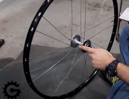
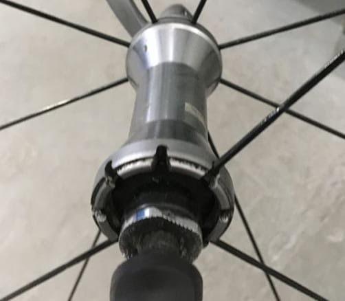
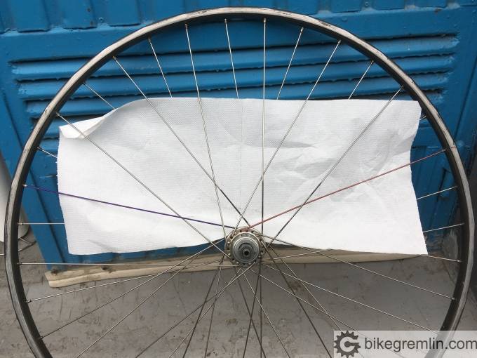
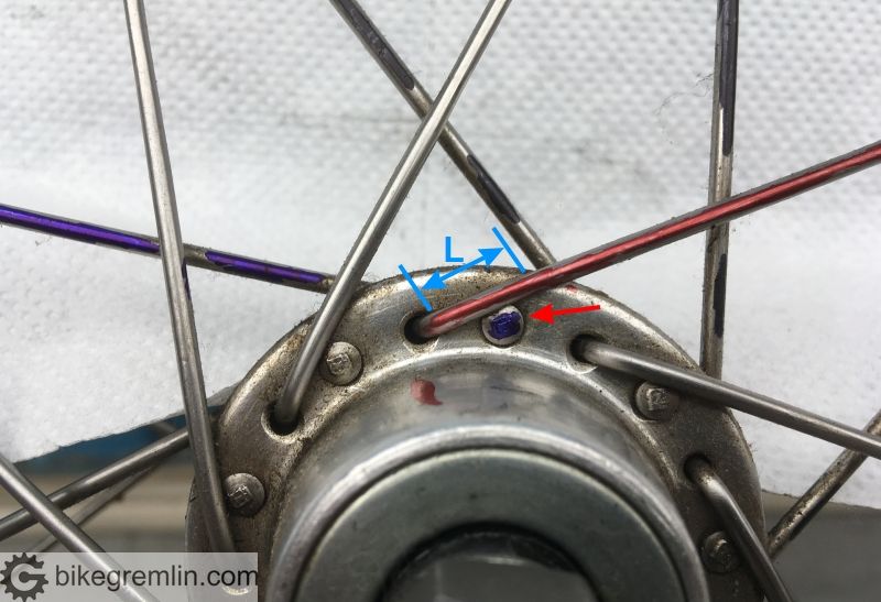
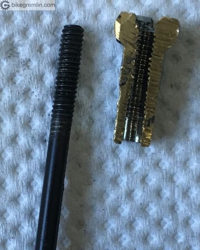
Here I must note that there are some “exotic” hubs that require “exotic” spokes – that, in turn, sometimes require “exotic” rims as well. Here’s an example:
Picture 1

Picture 2
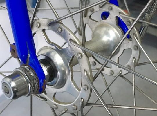
Picture 3
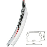
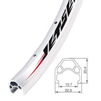
2.2. Rims
For rims it is important that they have the same number of spoke holes as the chosen hubs (and vice-versa).
I think that double walled aluminium rims are among the stronger, more durable, yet not too expensive, nor too heavy.
2.3. Spokes
Inexpensive and good quality solution are the standard, with a “J” bend at the elbow, 2 mm thick, ideally thinned down in the mid-section to 1.8 mm. Such spokes are also called “swaged” (some spoke manufacturers, like DT Swiss, refer to such spokes as “double butted“, while the ones that have wider elbow part compared to the nipple thread part, with still having narrowed down mid section are referred to as “triple butted“).
2 mm swaged spokes thinned down to 1.5 mm twist a lot when they are tightened, making the wheel build very difficult, without providing much benefits.
Narrower spokes, with 1.8 mm diameter at the ends, are a bit lighter, “more aero” (the modern buzz-word), but are less durable. Some of these come thinned down in the middle (swaged) to 1.5 mm. In this case, 1.5 mm mid section doesn’t make building a wheel much harder (unlike with 2 mm spokes swaged to 1.5 in the middle), and it does make these spokes a bit less weak. Still, 2 mm spokes swagged to 1.8 mm in the middle are a lot stronger.
How does thinned down (swaged) mid section make a spoke stronger? By making a spoke more elastic in the mid-section, it acts as a kind of a shock absorber, thus relieving some stress from the spoke ends – which are the critical parts where spokes fail from material fatigue most often. Perhaps a bit counter-intuitive, but that’s how it is. It should also be noted that this thinning down is done at the factory, by rolling, not by grinding, so that the material structure is kept in tact, without creating a weak spot prone to material fatigue.
Related to spoke diameters (“thickness”), it is worth noting spokes that are 2.3 mm wide at the elbows, 1.8 mm in the mid section, and the standard 2 mm wide at the other end (where the threads are). Such as DT Swiss Alpine III (Amazon affiliate link). These spokes are the strongest available. They have both the swagged mid section (making them effectively stronger), and the most critical part, the elbows, are extra thick (2.3 mm). Elbows are the parts where spokes usually break. Beefier elbow is stronger in and of itself, but another benefit is that it fits better into hub flange holes, that are made very large nowadays – usually around 2.6 mm in diameter. Which prevents “normal” 2 mm wide spokes from sitting snugly.
With spokes, another important aspect is their length, but more on that later.
I’ve had great results with Sapim and DT Swiss spokes (Amazon affiliate links).
Note: modern spokes from most manufacturers are made with a head angle of 90 degrees, or even more obtuse (95 and similar).
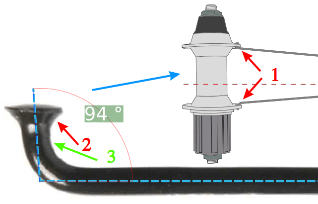
Spokes laced through hub flange holes (1), spoke head (2), and spoke elbow bend (3)
Picture 5
Picture 5 shows a spoke with J-bend (elbow) angle of 94 degrees. This design makes spoke (wheel) lacing faster and easier, and can help the spokes to be better seated when hub flange holes are too large (which is often the case). Sapim makes these angles 95 degrees, while DT Swiss goes with 90 degrees.
2.4. Nipples
Nipples should match the spokes. Spokes that are 2 mm wide at the threaded end will need nipples with 2 mm wide threads as well. Note that 2 mm nipples will fit 1.8 mm wide spokes, but the fit will not be strong enough and threads could get stripped under force. 1.8 mm wide nipples, on the other hand, will not fit 2 mm wide spokes, of course.
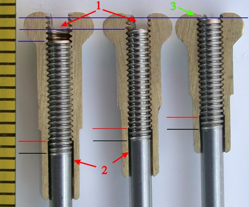
Nipple length of 12 mm is best in practice, unless the rim is exotic and needs longer nipples. Wheels are built most quickly with these and the interface is strong and durable. There are longer nipples available – notably 14 and 16 mm.
Note: Sapim and DT Swiss make their 14 and 16 mm nipples with longer thread. This is a poor design. Why? Spoke thread length is usually up to about 10 millimetres. If a nipple has longer threads, spoke won’t be able to come to the top of the nipple.
Source: Professional Guide to Wheel Building, by Roger Musson
Picture 6
The two nipples on the left in picture 6 (16 and 14 mm long respectively) can’t be screwed to the end, not without spoke body (without threads) getting stuck and burring the lower threads of the nipple. While leaving them as they are in the picture can result in the nipple head popping off during riding, because it has no support of the spoke in its top section, it is left hollow. I have experienced this: problem with using 14 and 16 mm long Sapim and DT Swiss nipples.
As for the material, there are aluminium and brass nipples. Aluminium ones are lighter, but also less strong and more prone to galvanic corrosion (Wikipedia article), so I avoid them.
3. Spoke lacing pattern
In this video, at 2:48, I explained the spoke lacing patterns (link should open YouTube, starting at 2:48). But here is the explanation in textual format.
I’ve also made a video explaining why wheels are laced and built the way it’s recommended here:

Exotics aside, there are two ways of lacing bicycle wheels: radially, and crossed. Before more detailed explanation, a couple of pictures that speak more than words:
Picture 7
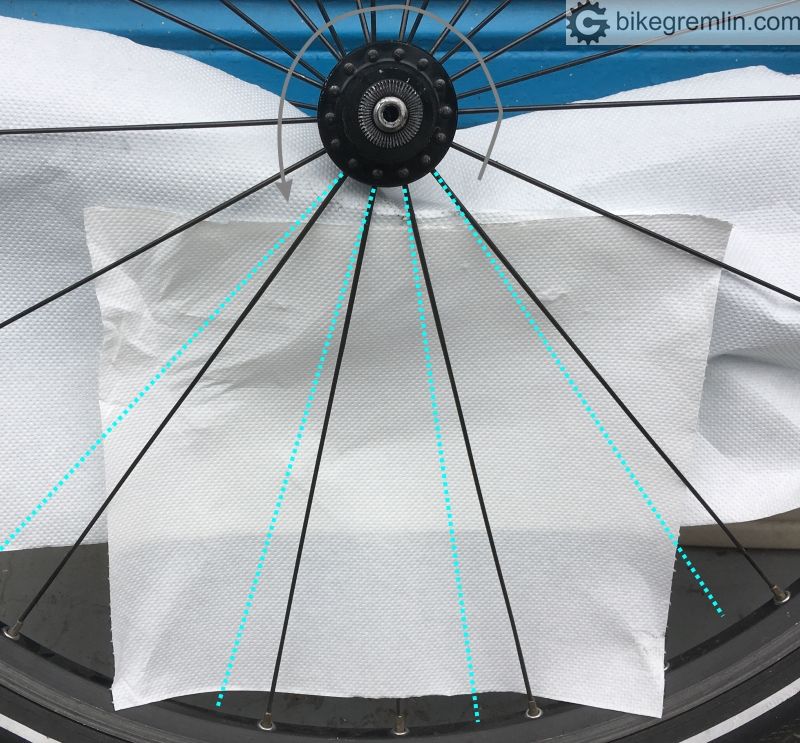
Radially laced wheels have spokes going straight from the hub to the nearest rim spoke hole.
Picture 8
Cross laced wheels have spokes going at an angle, to a spoke hole in the rim, crossing over other spokes on its way. The number of crosses can be smaller, or greater. More on that later, but our wheel has 4-cross lacing pattern.
Picture 9
When counting the number of crosses, people often miss the first crossed, adjacent spoke (painted in blue in picture 9).
All else being equal, cross laced wheels can take a lot more load than radially laced ones. Radial lacing is practically only used for show (and minimal weight savings since they require shorter spokes). I’ll explain why.
3.1. How cross laced wheels carry load
There are two main types of wheel loads. One is the torque, where hub tries to rotate on its axle, relative to the rim (in case of pedalling), or, when braking using disc brakes, the rim tries to rotate relative to the hub.
Picture 10 shows an example of pedalling force – wheel is depicted from the left hand side. When braking using disc brakes, the force acts in the opposite direction, by ground “pushing” against the rim.
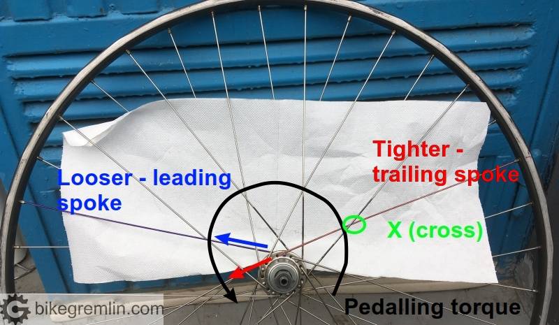
Picture 10
Spokes being pulled (trailing spokes) get tightened, while the ones laced in the opposite direction (leading spokes) get a bit less tight (loosened). Number of crosses can be smaller, or greater.
The part where the trailing and leading spokes cross, is the place where the further tightened trailing spokes push stronger against the leading spokes, thus reducing the amount of loosening that trailing spokes face – which is one of the benefits of the crossed lacing pattern.
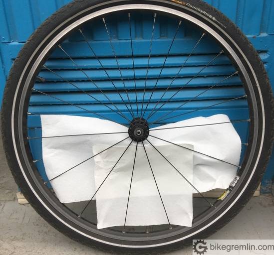
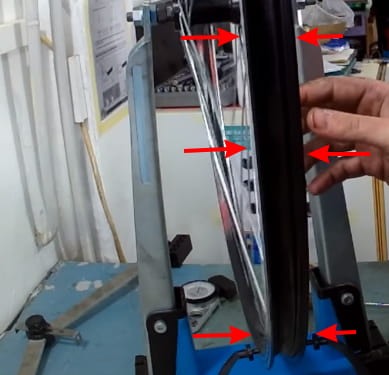
The other force faced is lateral movement of the rim, relative to the hub – usually by ground pushing against the rim, over the tyre, of course.
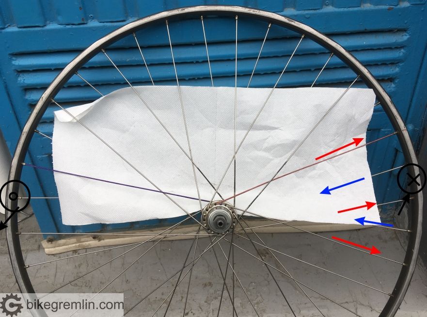
Picture 11
For an example, look at picture 11 and imagine the force acting on the right hand side of the rim, in the direction from the viewer, towards the blue door in the background. The spokes near the point where the force is used will be mostly affected. The ones closer to the door will become loosened (since the rim is moving towards them), while the ones closer to the viewer will be tightened.
To better resist such forces, spokes are laced at an angle relative to the hub, so that the hub’s flanges can be used as a lever, to oppose this force.
Picture 12
The greater the spoke angle (i.e. the more spoke crosses there are), the better will a wheel cope with lateral loads. Imagine if the red spoke in picture 12 were going all the way across the head of the adjacent spoke (painted blue and marked with a red arrow). That would make an even longer lever. However, that would make replacing a broken spoke difficult, because the access would be blocked. Also, head of the spoke would create a bend, kink, in the spoke going over it, making it weaker. That is why it is important to choose the optimal number of crosses. Picture 12 shows just a bit of overlap – borderline acceptable amount.
3.2. The optimal number of crosses
The number of crosses should be such that the maximum angle of spoke relative to the rim is achieved, but without the spoke going over the head of the adjacent spoke.
The actual number of crosses that achieves this mostly depends on the total number of spokes (and on the hub flange and rim diameter, to a lesser extent). How so?
A 36 spoked wheel has each rim spoke hole at 10 degrees angle (360/36), while each hub spoke hole on each side is at twice that angle (since half spokes go from one side, the other half from the opposite hub side).
If we took a 20 spoked wheel, each rim spoke hole would be at an 18 degree angle, with hub flange holes being at 36 degrees from each other.
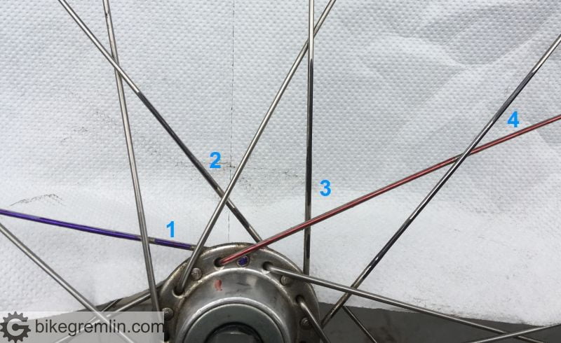
Spokes go in groups by 4:
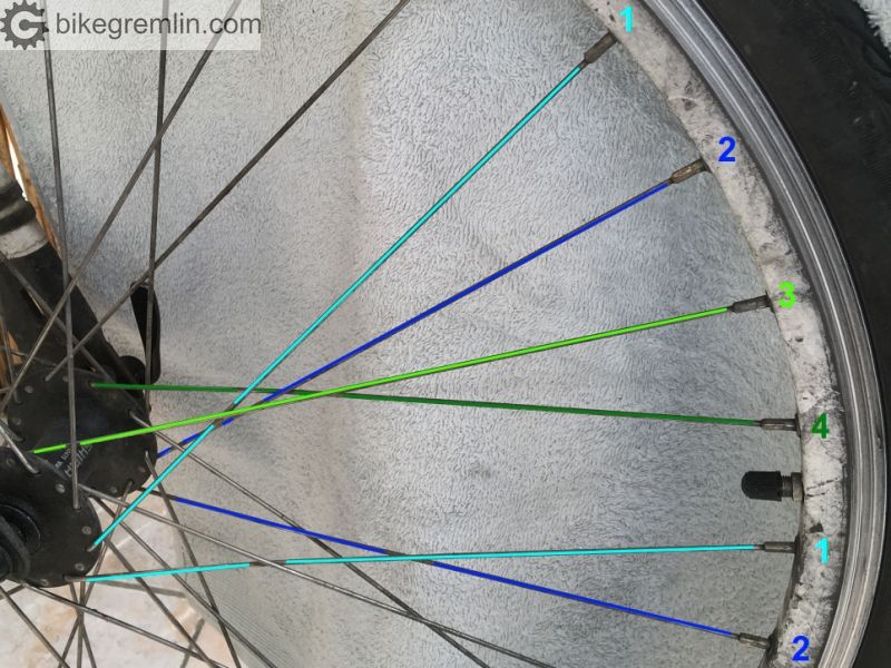
Picture 13
First come two trailing (or leading) spokes – one from each hub side.
Then two leading (or trailing) spokes – one from each hub side.
And so on – no matter how many spokes there are in total, and regardless of the number of crosses – this 4 group lacing pattern always exists.
Crossed spokes are 1 and 3, as well as 2 and 4.
To calculate spoke angle, one must multiply the number of crosses, by the hub flange angle. For a 36 spoked wheel, that would be 20 degrees multiplied by the number of crossings.
But how to tell when it is too much and when there will be spoke head overlap? For most rims and hubs, angle below 75 degrees does not lead to any spoke head overlap.
Another important aspect is to avoid the spokes entering the rim at a very steep angle (ideally stay below 7 degrees – though 8 is also OK), along with avoiding spokes overlapping the adjacent spoke holes (at the flange).
Simple, practical way of determining the optimal number of spoke crosses:
Divide the total number of spokes by 9, then round down to the first whole number.
Exceptions are 36 spoked wheels where with 4 across (36/9) you will often get some overlap, like shown in picture 12. And 16 spoked wheels, where you can get away with 2 across (because hub flange holes are at a great angle and distance.
To make things easier, here’s a table (note – for the really small rims such as 24″ or smaller, and for the really big hubs such as electric motor hubs, you might have to reduce the below given numbers by 1):
| Spoke count | Optimal number of crosses |
| 16 | 1 x (2 x sometimes) |
| 20 | 2 x |
| 24 | 2 x |
| 28 | 3 x |
| 32 | 3 x |
| 36 | 3 x (4x sometimes) |
| 40 | 4 x |
| 48 | 4 x |
3.3. How radially laced wheels carry load
Poorly!
With radially laced wheels, there is some (not naked eye visible) hub twisting, giving a poor copy of cross laced spoke pattern for load bearing. In the picture below, I drew the spoke position, when they are stretched (in the direction depending on the force direction). It is exaggerated in order to demonstrate (and I didn’t re-draw the whole rim as it moves with the spokes).
Picture 14
There’s a lot more twisting and friction, which can break spokes. That is why only front wheels for rim brake bicycles are sometimes laced this way (and non-drive side of some exotic rear wheels).
Another downside of this lacing pattern is that it puts a lot of stress on the hub, with spokes trying to rip it apart. Note in the picture below how cross laced wheel spoke tension practically tries to compress the hub flange material, while radially laced wheel’s spokes are trying to pull it outwards, rip it apart:
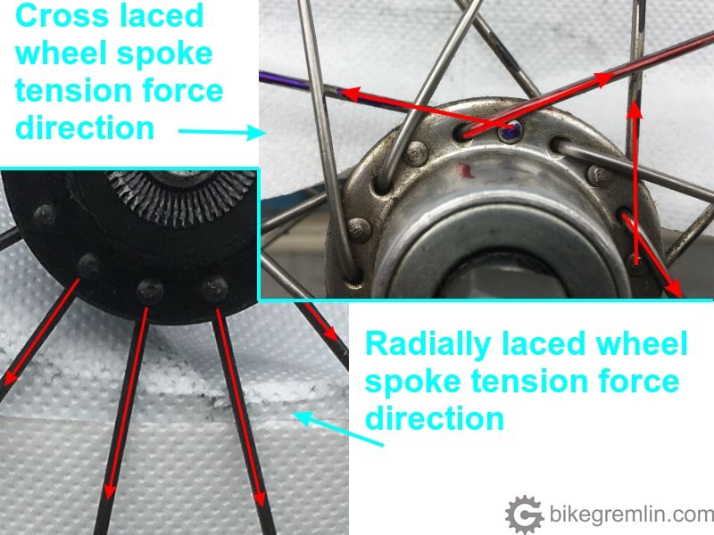
Picture 15
Here is my video showing how to lace a wheel:
![Bicycle wheel building [04] - Spoke and rim preparation, and lacing the spokes [1005]](https://bike.bikegremlin.com/wp-content/plugins/wp-youtube-lyte/lyteCache.php?origThumbUrl=https%3A%2F%2Fi.ytimg.com%2Fvi%2FrSlydFsrIW0%2F0.jpg)
4. Why optimal spoke length is important
Ideally, spoke length should be such that the entire length of nipple’s threads is used for carrying the load. Besides, on rims that are not double walled, spokes that are too long will protrude from the nipples and could puncture the tube. I cut a nipple in half to demonstrate this. Marked nipple and spoke thread start and finish, since it’s not clear in every picture.
Picture 16
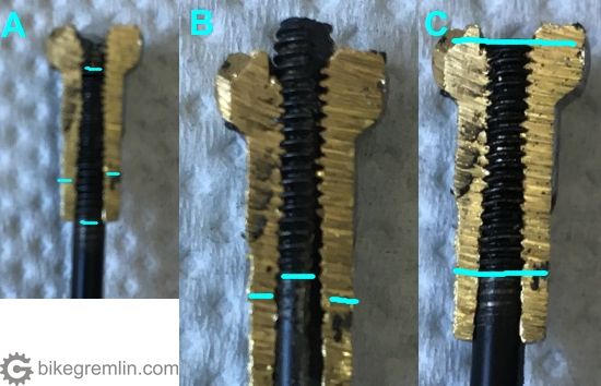
Picture 17
5. Calculating optimal spoke length
In order to calculate the optimal spoke length, the following measurements are needed:
- Effective rim diameter (ERD) and other important rim measures.
- Important hub dimensions (flange diameter etc).
- Diameter (thickness) of spokes (thinner ones elongate more when tightened).
- Number of spokes and the number of crosses.
I explained the number of crosses in this post, while for other terms I’ll be adding links as I publish relevant articles.
Finally, all the measures should be entered in a spoke length calculator (link is towards the one I mostly use).
Update, December 2023:
New version of the spoke length calculator:
https://spokelength-project.com/calculator/
6. The importance of achieving uniform spoke tension
When spokes don’t have a uniform tension, i.e. when some are significantly tighter, and others much looser, what happens?
- Spokes that are tighter will carry more load than the looser spokes. Hence being more stressed, and also putting more stress on the spots where they are connected to the hub (at the flange) and the rim (where the spoke nipple is).
- Looser spokes will be even looser as the wheel is ridden – when they are at the bottom (during every wheel revolution), and when the wheel is loaded in such way that they get lower tension (side loads from the opposite side for example). This will result in them, since they are already loose(r), having more (micro) bending and they will be more likely to break at the elbow, due to stress (fatigue).
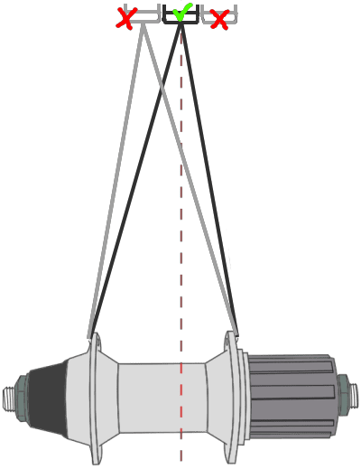
With rear hubs, and the front ones on disc wheels, there is a caveat:
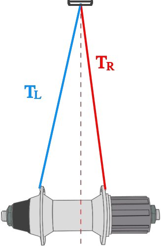
Picture 18
Right hand side spokes on the above noted hubs, have higher tension than the left hand side spokes, because their angle is sharper and the rim wouldn’t be centred otherwise. However, tension of right hand side spokes should be as even as possible, when compared to the other spokes on the same side (right hand side). Same goes for the left hand side spokes – they should have an uniform tension when compared among them.
When building a wheel and choosing between 100% true rim, and more even spoke tension, go for the even tension. Wheel built that way may not be 100% straight from the start, but it will remain as it was even after 20.000 kilometres (unless a rim is dented/bent by hitting a rock). On the other hand, if a wheel is built to be 100% true, but with uneven spoke tension, it will come out of true relatively quickly, and spokes are more likely to break on such a wheel.
With another caveat: the rim should be true within the acceptable tolerances – as explained in the next chapter. That is: 100% uniform spoke tension is not good either, if it results with the rim being too much out of true.
How to measure and compare spoke tension?
Guitar pluck can be used to pluck the spokes and get the tension surprisingly uniform by comparing sound uniformity – like plucking guitar strings.
To me it is a lot faster and easier using a proper spoke tensiometer. I’m not very musical, plus plucking the spokes does not give the information of how high the tension is (only how uniform it is) – which is often important (70 kilopond is the minimum for most wheels). Most tensiometers are not very precise. Exception is this patent (designed by late Jobst Brandt), sold by Wheel Fanatyk. Or a more affordable variant, made by our Macedonian brother Filip Kralyevski – tensiometer.
7. Acceptable tolerances when building a bicycle wheel
Nothing in this world is perfect – not even the bicycle wheels (it is just as close as it gets to that 🙂 ). In mechanics, things are usually built within the acceptable tolerances. What are those when it comes to bicycle wheels, i.e. when is a wheel considered acceptably true and well built?
We will first define the terms: “radial trueness“, “lateral trueness“, “rim dish trueness“, while “spoke tension evenness” is already explained in the previous chapter.
7.1. Radial trueness
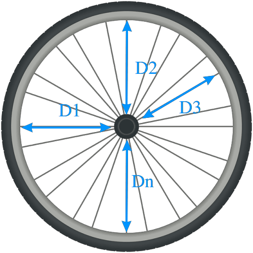
Picture 19
Rim distance from the wheel’s centre should be even along the entire rim’s circumference. Ideally:
D1 = D2 = D3 = … = Dn
Video where I demonstrate wheel radial truing.
Of course it will not be ideal, but it is important to keep within the acceptable tolerances (defined in chapter 7.4).
Until you get the feel for visually determining the gaps when checking on a truing stand, you could use feeler gauges (Amazon affiliate link).
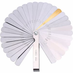
Click the image for shopping on Amazon (affiliate link)
Picture 20
7.2. Lateral trueness
Lateral (un)trueness is what we all notice first – how much does the wheel wobble (sideways).
Picture 21
Here too you could use the above noted feeler gauges to measure the deviation, at least until you get the feeling.
7.3. Rim dish trueness
In this case, picture 22 speaks more than a 1000 words:
Picture 22
This is measured using wheel dish measuring tool (Amazon affiliate link).
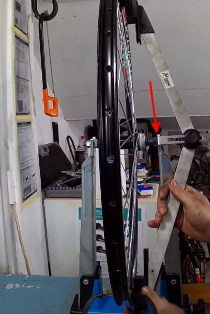
Measuring hub locknut (see OLD explained on this link) distance from the rim on each side, then comparing if it is even
Picture 23
There are some caveats here as well. For the “exotic” stuff, see on this page the explanation what to do when using asymmetric rims, and/or offset frames.
7.4. Acceptable trueness, and spoke tension tolerances
Briefly, a list of acceptable tolerances for the above explained parameters:
- Spoke tension uniformity (between spokes on the same side): up to +- 10% tension variation among the spokes (on the same side). Ideally +- 5%, so that the maximum tension difference between the tightest and the most loose spoke is up to 10%.
- Radial trueness: up to +- 0.5 mm deviation.
- Lateral trueness: up to +- 0.25 mm deviation.
- Rim dish trueness: up to 0.5 mm left-right deviation (dish gauge will always show the deviation as doubled!)
8. Sources – highly recommended
- Jobst Brandt – The Bicycle Wheel (Amazon affiliate link)
- Sheldon Brown – Wheelbuilding
- Roger Musson – Professional Guide to Wheel Building
- My series of videos on bicycle wheel building.
- Spoke length calculator:
https://spokelength-project.com/calculator/
Last updated:
Originally published:
The existing comments posted under this article (questions and answers) have been moved to this BikeGremlin forum thread:
https://www.bikegremlin.net/threads/bicycle-wheel-building-basics-article-comments.133/
Good stuff, clear and concise…thanks.
By far the best and complete information regarding wheels.
I learned by myself to first true wheels and later build some.
I work in the bicycle business for the past 35 years now.
Great job!
Excellent travail de rédaction.
Je suis autodidacte dans l’assemblage de roue de vélo depuis 35 ans.
Il s’agit et de loin du document le plus complet sur la dissection de la roue de vélo!
I have a spain 14mm nipple in hand, the problem you describe does not happen, the spoke does go in the nipple all the way through with 0.1 mm sticking out of the nipple.
Hi Radu,
Depending on how long the threads on a spoke are – I suppose that could be possible.
It is also possible Sapim have changed their nipple design.
My last batch of nipples is about 1-year old, by DT Swiss, while my leftover Sapim nipples are about 2-years old now.
At this moment, I can’t order (source) any new Sapim nipples in my country, to put this to the test.
In my experience so far: 14, and especially 16 mm long nipples from Sapim and DT Swiss don’t let most (Sapim and DT Swiss) spokes get threaded all the way to the top of the nipple, without the non-threaded part of the spoke coming against the nipple threads and making the screwing in more difficult (and damaging the nipple threads at the bottom of the nipple).
If a spoke threads all the way to the top of the nipple without any binding, or resistance – then there’s nothing to worry about.
If it doesn’t, I think the lesser of two evils is having some nipple thread damage, compared to leaving the top part of the nipple without the spoke (i.e. going with shorter spokes), because the top of the nipple would then be unsupported and could break off.
Relja
not sure how old the ones i have are, i got them yesterday, but they do go all the way to the top of the nipple only by hand, maybe they did fix the problem. ( i tested with sapim nipple with 290mmx2mm sapim spokes )
Roger Musson, in his book on bicycle wheel building, explains that only DT Swiss spokes have that problem (or a “feature”).
However, I made the picture at this link:
https://bike.bikegremlin.com/8431/custom-wheel/#2.2
using Sapim spokes (as noted in the picture) I bought from the local official Sapim distributor.
In that article, I also explained how this “feature” can be useful if one can’t source long enough spokes…
…and how that can result with a nipple failure if the rider is heavy and strong. 🙁
thank you for your precious suggestions. I’m about to build my first wheel.
Cool.
Enjoy it. 🙂
Hi Relja, very interesting reading on your wheel building articles,I totaly agree with you there is no need for exotic hubs and fancy spoke patterns,I have never had any problems with a 32 hole rim or a 36 hole rim ,I am now building a few of my own wheels using alex R450 road rims with 32 hole cross 3 spoke pattern using the standard j-bend 14 gauge spokes,I see sapim polyax nipples have a slighty curved head where they sit on the rim and most other spoke nipples sit flat on the rim,do you have any advice on what spoke nipples to use,i will be using stainless steel j-bend spokes with brass nipples but i am still not sure whether to go with dt swiss brass nipples or sapim polyax nipples,what a wonderful piece of engineering bicycle wheels are.
Hi Mike,
EDIT:
Disclaimer
Many cycling enthusiasts, mechanics, magazines, and manufacturers seem to think differently.
Still, until I find a good theoretical and practically proven (verifiable) explanation, this is my opinion, based on my education (theoretical knowledge) and experience.
/ disclaimer end
When it comes to nipples, I go for either SAPIM, or DT Swiss 12 mm brass nipples.
I had to google the Polyax nipples (and found their page). 🙂 The “ball-joint” shape of Polyax nipples is a marketing gimmick – in fact, such a convex shape reduces the nipple-to-rim contact area (resulting in the load distribution over a smaller area), while I don’t see any advantage over the standard (flat, but at an angle) nipple design when it comes to nipple alignment. Not in practice.
Standard nipples work perfectly fine. So my choice is SAPIM “Flat head” (didn’t know they’re called that way 🙂 ) or DT Swiss Pro – even though the DT Swiss ones have the nonsense convex shape as well, but when I can’t find any SAPIM ones, they get the job done better than any locally available low-end Chinese nipples.
The round head of the Polyax nipples is designed to avoid having a bent spoke, i.e. the spoke is in the right direction from the start…
Hi Relja thanks for your valuable information,it makes sence with those sapim polyax spoke nipples they would have less contact area on the rims,just about all rims i have pulled apart all have a flat contact area with the spoke head at the rim,so i will go with the standard flat head nipples cheers
i dont like any alloy nipples as they corode very fast and they are the most difficult spoke nipple to use,those brass ones are very durable and tough.
Hi relja,i did some more research on those sapim polyax ball joint nipples and i could only find one decent article on them where one wheel builder used them with curvy type nipple washers and on rims with convex shaped eylets,maybe thats the only situation where they are used,but i have hardly seen anyone putting washers on with nipples as most just go and buy a strong rim and just use brass nipples,the flat head ones do have just a slight angle and they are sold as standard nipples,cheers
Hi Relja,just completed my first double walled alloy rim build,i have allways used the older araya box rims but thought i would give a retro bike a new look.i went with the 14 gauge 14mm long standard brass nipples due to a better look,i followed the lacing pattern on this website,spokecalc.io and the build went very smoothly following this pattern,its a very similar pattern to the way sheldon brown built his wheels,all trailing spokes heads inside the hub flange,this way makes for a much stronger build,my double walled rim looked like the spoke holes were all running down the centre of the rim,but on close inspection they were ever so slightly of to the left and right,not as easy to follow as those old school araya rims,i found this method on spokecalc.io very easy to follow and wheel build did not take very long,after reading so many pages on the wheelbuilding topic i can see every builder has a different way of building wheels,i salvaged an older joytech raceing hub,i used stainless steel spokes from another wheel and just had to go buy new brass nipples and new rims,those older hubs will run for another 20 years,i really dont like any of those new hubs with sealed bearings,so my wheel is now half retro style and half 2022 style it looks awesome cheers
Hi Mike,
Glad to hear the build went well.
Regarding the trailing/leading spoke facing:
I think it’s more of a topic for an academic discussion, than it really makes any measurable difference in terms of wheel strength.
If there is an advantage to Sheldon’s preferred lacing pattern, it is that chain may be less likely to get badly stuck between the spokes and the cassette in case it drops.
Why?
Because when the trailing spokes go along the inside of the flange, then pedalling torque pushes the spokes outwards a bit, instead of pulling them a bit inwards, so there’s a bit less of a probability that the chain will get more deeply down, and then pressed harder against the cassette, once the pedalling torque is gone.
In practice, I don’t see much of a difference, and a chain going off is a mess either way (at least in my experience). I just make sure to keep my rear derailleur limit screws properly adjusted. 🙂
Edit:
Of course, there’s nothing wrong with Sheldon’s lacing pattern. My commute-haul-everything bicycle’s rear wheel is laced using that pattern and it’s been good for the last decade, even with frequent heavy loads and very bumpy roads.
correction i think that was all trailing spoke elbows inside the hub flange
I will miss my old araya rims,those old box rims certainly do the job for so many years and they did smooth out the road vibration better than anything i have used,they were a high end rim in their day,quiet remarkable performance for a single walled rim,not long after those araya rims came out they made double walled eyleted box rims,these modern day double walled alloy rims dont smooth out the bumps as good,so we fix that by running good tyres,cheers
In case, you haven’t a tension meter to measure the tension, you can also estimate by feeling it with your hand. Use your thumb and index finger to try separating the spokes where they cross, and take note of how far you can spread the spokes.
Hi Zoe,
Thanks for the tip.
I find that method to be the least precise (prefer using a guitar pluck, if there’s no tension meter), but have used it very often in a pinch, especially in the field, so I’d say that it does work.
Relja
Thanks for sharing. It doesn’t need to be 100% accurate, so just do my best to make the tension setting as close to uniform as I can.
Hi Zoe,
I completely agree. Since rims are not 100% accurate, even with the most precise tension meter, you can’t get the tension to be 100% uniform, while the rim is being acceptably true. I always aim for the rim to be within the acceptable tolerances (as listed in the article), with tension as uniform as possible for that.
Relja
Hi Relja,i use a basic tension meter like the parktool tm-1 ,they are not 100 percent spot on but they do give a repeatable result,i check that my tension meter is not far out by using it on an older wheel that is never ridden and calibrate the tool off that,when i am 2/3rd of the way through my wheel build i will stop then equalize the spoke tensions,no you can never get each spoke perfect and no wheel is perfectly round but i usually can get each spoke within a 10 percent range of each other,i have tried not using a tension meter and tried plucking spokes and feeling the spokes with my hands but i did not even get the spokes close to correct tension using those methods,you dont need to build perfect wheels but you definatley cant go outside the exceptable tolerances,cheers