In this article I’ll explain bicycle frame design. Why do most frames come with a high horizontal top-tube, that is often difficult to step over when mounting, or dismounting? How are the modern frames made to be rather light, while still being strong enough?
The emphasis of this article is on weigth and strength. To understand how tube angles and dimensions affect ride characteristics and handling, se the article: Bicycle Frame Geometry.
For the info on materials, see: Bicycle frame materials – explained.
1. Bicycle frame design basics
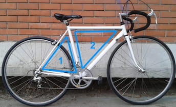
If you look at bicycle frames, you will notice that most models are based on two triangles:
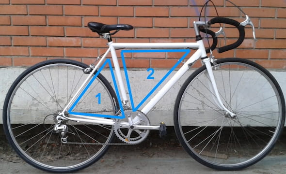
Picture 1
Over a hundred years of experience has shown that this construction gives the highest possible strength, with the thinnest (and lightest) possible tubes. At least when it is required to carry rider’s weight, pedalling force, pulling on the bars, and handle the road bumps.
Lighter, heavier? What we really measure is mass. Weight we measure when standing on a scale, is mass drawn by the Earth’s gravity. But that’s a topic for a separate post. For this one, we will say that weight = mass (sorry, Sir Newton).
Step-through frames, also called “women’s” bicycles, are a bit different:
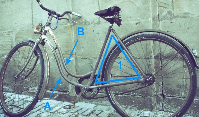
Picture 2
Step-through frames have only one, rear triangle. They are designed for more convenient getting on and off the bicycle, but that comes with a price: such design requires the tubes marked as “A” and “B” in picture 2 to be a lot stronger, thus heavier, to get decent frame strength, compared to using the two-triangles design. Sometimes step-through frames have only one very thick and heavy tube, instead of two, which is usually even worse in terms of total frame weigth.
Let’s repeat: if you want a frame to be as light as possible, while still being strong enough, build it using two triangles.
Old, classic frames had a horizontal top tube. Modern ones almost always have a sloped top tube.
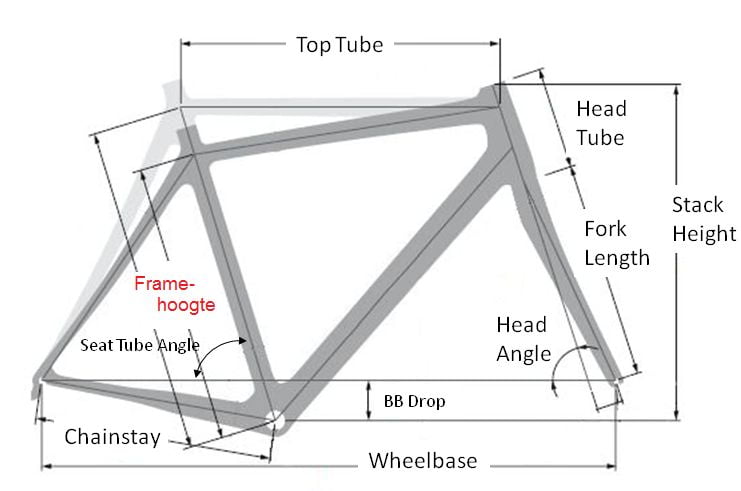
Light-gray frame has a horizontal top tube.
Dark-gray frame has an angled (“sloped”) top tube.
Picture 3
No matter how convincing the sales people may sound, techically there is no advantage in having an angled top tube. However, designing a frame with a horizontal top tube, so that all the other measurements are appropriate, takes a lot of knowledge and experience (see bicycle frame geometry article for details). It’s a lot easier to just slope the tube, and not care where it lines up.
2. Bicycle frame tube loads
Bicycle frame tubes are mostly compressed (compressive loads), bent, and twisted (torsion loads). They generally take no loads that are trying to stretch them.
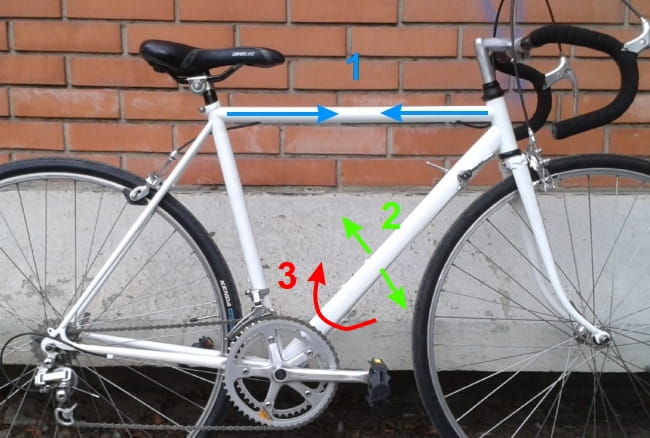
Picture 4
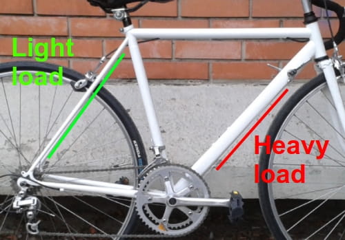
The highest load is taken by the down tube, and the lowest load is taken by the seatstays (rear triangle). This is obvious from comparing various tube thickness of the frame in the picture.
Picture 5
Seatstay tubes (marked green in picture 5) take so little load, that they are always a lot stronger and heavier than necessary! Why don’t they make them lighter? Because further thinning down of those tubes’ diameter, or walls, would make it impossible to weld, or glue them to the rest of the tubes. You still need some material to hold on to.
3. Forks
Here I’ll explain bicycle forks in terms of strength, weigth and load. For other important fork-related subjects, you can see:
- What is a bicycle fork, important dimensions, and types of forks.
- Names of bicycle fork parts and types of headset bearings.
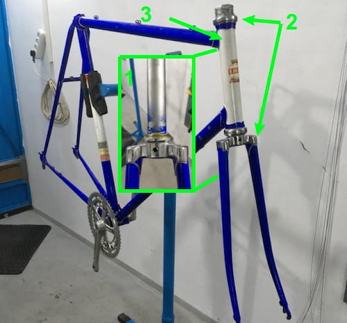
Bicycle fork has a relatively stong and stiff top part – the steerer column. It is placed inside the frame’s head tube and held in place by headset bearings.
Picture 6
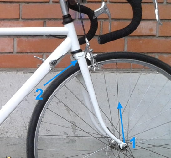
The top part is strong and well anchored, while the wheel exerts force on the fork from the bottom end, using the entire fork leg length as a lever. This is why fork gets most highly stressed and loaded at the section right below the head tube, where the legs start going out.
Picture 7
Forks often start cracking at the rear part, near the top (arrow 2 in picture 7). Width of the fork legs shown in picture 7 is a good indication of the amount of load taken by different fork leg sections. This is a good opportunity to bust some common myths, by providing some facts:
- Fork legs are thinner at the bottom to reduce weigth, because they don’t need so much strength down there. It’s not in order to make the fork-legs act as suspension springs.
- Legs are bent forward at the bottom in order to affect the fork trail, without altering the head tube angle. It’s not done for any shock-absorbing reasons.
Many modern forks are made with an angle at the very top, where the forks exit the head tube, with straigh legs. Especially suspension forks. This is done because the construction, or the materials used are not practical to make the narrowed down, and bent shape near the bottom.
3.1. Disc brake forks
What makes disc brake forks different, apart from having a disc brake caliper mount? Let’s first take a look how braking force is distributed with rim brakes:
Picture 8
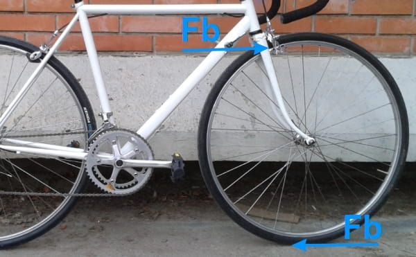
When the brake is applied, braking force, over the rim, tries to pull the brake caliper out of the fork, towards the front side, effectivelly pulling the fork forwards. The force is concentrated at the top part of the fork – where it is thick and strong, well supported by the head tube. Lower part of the fork legs is pushed towards the rear by the inerita of the slowing down rider and bicycle, bit in order to bend backwards, fork legs would simultaneously have to push the front part of the bicycle up a bit (see the curve). So this force, which isn’t too strong, is further negated by the very weigth and inertia of the rider and the bicycle.
Simply put: rim brakes don’t put much load on the fork.
What about disc brakes?
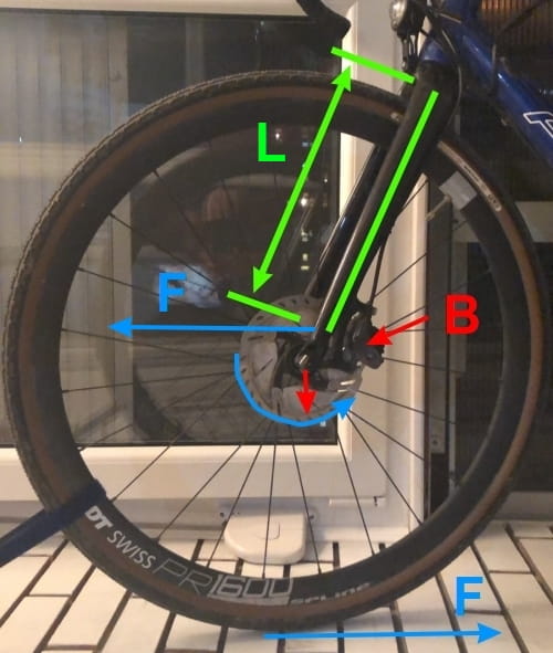
Picture 9
With disc brakes, almost entire fork length is used as a lever over which the braking force loads the top part of the fork (L in picture 9).
At the same time, as the wheel and the brake disc are trying to turn, brake caliper is holding up the disc, effectivelly acting as a fulcrum, around which the wheel attempts to turn, which exerts a downward pulling force, trying to get the wheel out of the dropout. Thru axles prevent this, but open ended forks should regularly be ckecked for the tightness of the wheel holding bolts, or quick-release levers. This doesn’t happen at once, but after many micro-movements, because bolts have a tendency of turning in the direction of lower preload, whenever they get moving.
In addition to that, braking force pushes the brake caliper forward, while trying to pull the bottom of the fork backwards – exerting some bending force at the fork’s lowest part.
This is why disc brake forks need to be a lot stronger and heavier than rim brake forks.
Article that explains other disc brake pros and cons.
4. Tubes: strength and weigth
Why are bicycle frames made of tubes, not of rods?
A tube is a rod with a hole! 🙂
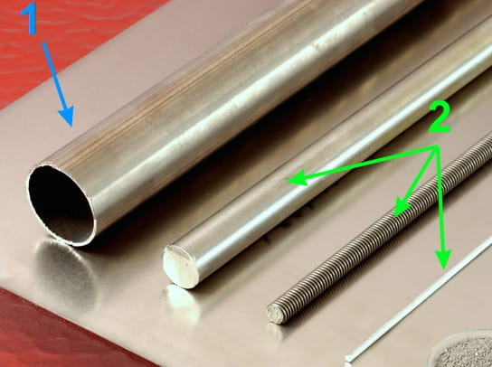
Source: CSIRO
Picture 10
Remember the 2nd chapter, about the types of loads that bicycle frames face. Before the boring theory, a practical example:Say we wish to make a frame that is as light as possible, while being strong enough to carry us. To keep it simple, let’s try doing it with steel (more on various frame materials in a separate article). Let’s begin:
We could try rods with a 2 cm diameter (thickness). Let’s see… hmm… those are quite heavy. Should we go with thinner ones? Bugger – now it’s too flexy! I know, we’ll try the 100+ year old trick: let’s use tubes!
If we take 3 cm wide tubes, with walls 6 mm thick, we’ll get a stiffer, stronger and lighter construction! Great.
Let’s see about 4 cm wide tubes with 3 mm wall thicnkess. Uuuh – even lighter, and a bit stiffer and stronger.
Let’s go crazy – 5 cm wide, with 0.1 mm wall thickness! What’s this? They can’t be welded together! They dent easily if you hit them!
Let’s explain what happened here – and why.
First thing to note is that a 2 cm wide rod is stronger and stiffer than a tube of the same diameter. However, with an increase in diameter, both strength and stiffness also increase drastically. So a wider tube can have relatively thin walls, that make it quite light, and still be as strong and stiff, as a lot heavier (and thinner) rod.
The ratio is about this: tube’s stiffness increases by the third power of the increase in diameter. If we compare two tubes with the same wall thickness, one having a 2 cm (d1), the other having a 4 cm (d2) diameter, then the second tube will be 8 times stiffer.
(d2-d1)3
The second tube in this example will be 8 times stiffer, but also 2 times heavier. We could reduce its wall thickness (keeping the outer diameter unchanged). This will make it a bit less stiff, and a lot lighter. However, even if the stiffness is cut in half, that’s still 4 times stiffer than the first tube – yet lighter! Increasing a tube’s diameter increases its stiffness a lot more than thinning down the tube walls decreases stiffness.
But – there is a limit of how thin the walls can be. Below a certain wall thickness, tubes can’t be welded together (they just burn through). Likewise, walls that are too thin result in a tube that is too easily dented from the slightest blow. Now I’ll use another example:
Take a small Coca-Cola can. Put it upright, on the ground. Stand on it gently, and slowly transfer your weight on it. If you make sure to keep the load vertical, and do this gradually, it may hold your weight. However, if you put a dent in the can’s walls, even the slightest, before attempting this – it will quickly and easily get squashed.
What has this got to do with bicycle frames? Bicycle frame tubes, like all the other tubes, loose a lot of their strength if their walls get dented. This goes especially for the down tube, and the right chainstay.
4.1. Butted tubes
You will often read this in brochures for expensive aluminium, or steel frames: double, or triple butted tubes. What does it mean?

Picture 11
Remember the problem of welding the tubes with walls that are too thin? What if we make the tube ends a bit thicker-walled, and make the mid section with thinner walls? That’s what this technique boils down to.
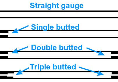
Picture 12
This technique does raise the tube production costs, but it enables making the frames even lighter, yet almost just as strong.
5. Conclusion
Has this article helped you understand why bicycle frames are built the way they are – and why I recommend against buying 2nd hand bikes with dented tubes?
I tried to explain the basic challenges frame designers need to overcome. In a separate article I write about the pros and cons of various frame materials.
6. Sources
Last updated:
Originally published:
The existing comments posted under this article (questions and answers) have been moved to this BikeGremlin forum thread:
https://www.bikegremlin.net/threads/bicycle-frame-design-explained-article-comments.145/

If you were to draw a freebody diagram, I think you will find that the chain stay and the down tube are subjected to tension (stretching force). While I am not expert on bikes, I am reasonably certain that would be the case. In addition, the downtube will be subjected to torsion due to the offset of the pedal force from the bike mid plane and will be reacted by the forces on the handle bar (which is again offset from the centre plane). That I think explains why the down tube is usually the most heavy member (because it is subjected to a tension force and an additional torsion).
Good points. I agree. My reasoning:
I think that chainstays see tension most of the time, except for the right chainstay when pedalling really hard.
Seat tube is in compression when the rider is seated, and under tension when they are standing on the pedals.
Tubes of a larger diameter see some torsion as well, which is one of the reasons for them having a larger diameter (yes, wall thickness does vary, but still, the overall stiffness and strenght do increase with greater diameter, with most tube designes). Especially the downtube – as you noted.
I would argue that the highest loads are tension and torsion loads (and the tubes facing those are of a greater diameter). However, it’s fair to note that I have no way of accurately measuring that, especially since it only makes sense to measure while a rider is riding, jumping, sprinting etc, so take this with a grain (or a bucket 🙂 ) of salt.
What criteria determine the shape and location of rear derailleur dropouts? why are there so many designs of replaceable dropout ears?
Hi Paul,
That’s a very logical and reasonable question, but the answer may be disappointing.
I wouldn’t bet my life on it, but I’m pretty certain that it’s just the carelesness of parts and frames manufacturers.
Combined with a pinch of greed perhaps, because if a replaceable RD hanger is uniform (or if there are only a few different types), no one would be able to sell one for $10 or more. Case in point:
https://www.bike24.com/p2511174.html
https://www.giant-bicycles.com/gb/giant-road-rear-derailleur-hanger
too many newer bikes do have expendable parts,now i am not saying all new bikes are trash but too many bikes have parts that break or wear out fast which is why i ride old school retro style bikes,once you fix them up good you do not have to work on them for a very long time,those older bikes are ten times more reliable then some of these newer ones
why would they even make alloy rear derailer hangers when all previous bikes had them built into the rear steel dropouts,that was one step backwards for bikes,another step backwards for bikes was moving over to all sealed bearings,while it may be good for the manufactures bottom line its no use to bike riders,try even finding the right sealed bearing for your bike when they wear out,then try fitting one,i had a friend bring me a bike not even 10 years old and all sealed bearing were done including the headstem.
Hi Mike,
Regarding RD hangers, steel can be bent back more times than aluminium. For aluminium (and carbon) frames, as Paul said, I think a separate hanger is a good idea in terms of durability.
Also, the separate hangers are designed to be weaker, so they “give in” first in case of an accident – protecting the rest of the frame, and even the rear derailleur from the impact.
My biggest gripe is that manufacturers didn’t bother to accept one (or three for that matter) hanger shape standard – so finding a spare, matching one is difficult. That’s the biggest nonsense.
Regarding cartridge bearings – they have pros and cons. I very much prefer cup and cone. My video on cartridge bearings vs cup and cone.
i switched over to a sealed bottom bracket and found they do run alot smoother and alot less work,but when it comes to wheels and headsets i still use cup and cone system,easy to work on those and easy to find spare bearingswhen i was using cup and cone bottom bracket i found it too fiddly to adjust and no matter what type of grease i used there the grease would allways move away from where it was needed
Your dropout comment is valid perhaps for steel, aluminum and titanium frames, but for carbon fibre a separate solid dropout which can be threaded is mandatory.
This is an edit to the post I made a few minutes ago with a different logic. I think it would be best if you only “publish” this one: Are 1) seat stays assymmetric in shape and 2) do the drive side chainstay and the drive side seatstay sit more outboard (from the bike center / bb Center / wheel center) than their non-drive side counterparts? Assumption for my conclusion: the wheel sits in the center of the bottom braket and is perpendicular to the bottom bracket. My conclusion is that both (1) and (2) must bet true because 1) the center of the rear wheel is closer to the non drive side dropout than to the drive side dropout (see pictures above the headline “2 Visual Test” on https://www.parktool.com/en-int/blog/repair-help/wheel-dishing-centering) and 2) the wheel is / should be centered between the seat stays near the seat tube (see first picture on the same parktool URL above below the headline “2 Visual Test”). Is there a flaw in my thinking?
Context: I’m designing a custom bike for myself with the rear rack welded to the frame. Ideally I would want to have the same distance between the tire and the inner edges of the rack on the drive and non drive side….
Hi Nic,
Most frames have symmetrical dropouts (equal distance from both the longitudinal and transverse frame axes). With such frames, the rear wheel is dished so that the rim’s centre is right between the hub’s “locknuts” (quotation marks are because many modern hubs don’t have classic locknuts, just the hub ends that face the inside of the frame’s dropouts). See picture 22 in my Bicycle wheel building basics article.
There are however “offset frames,” where the drive side dropout is a bit further to the right (i.e. placed more outwards from the frame’s longitudinal axis compared to the non-drive side dropout). That is done to help make the rear wheel stronger, as it allows spokes coming from the drive-side flange to not have such a steep angle, thus making the drive and non-drive side spoke tension more similar (less drastic difference in tension), plus it provides a better bracing angle for the drive side spokes.
For the bike to steer nicely, the rims (and the tyres) need to be in line with the bike’s longitudinal axis. Hence, if your goal is to have the same distance of the tyre from both dropouts, it would make sense to make the dropouts symmetrical (i.e. to not make an offset frame).
Relja
P.S.
As English is not my native, and this topic is a bit complex for me to explain with words, I asked Grammarly’s new AI tool to read what I wrote, and make it easier to understand. This is how Grammarly’s “robot” rewrote my reply – in case it’s easier to understand (I’m curious to hear if it really was helpful):
Dear Nic,
I hope this message finds you well. I wanted to bring to your attention an interesting fact about bike frames. Most bike frames have symmetrical dropouts, meaning that the longitudinal and transverse frame axes are equidistant from the rear wheel. In this case, the rear wheel is dished so that the rim’s center is right between the hub’s “locknuts.” You can find a visual representation of this in picture 22 of my article on Bicycle Wheel Building Basics.
However, there are also “offset frames” where the drive side dropout is a bit further to the right, placed more outward from the frame’s longitudinal axis compared to the non-drive side dropout. This design is meant to make the rear wheel stronger. It allows spokes coming from the drive-side flange to not have such a steep angle, making the drive and non-drive side spoke tension more similar and providing a better bracing angle for the drive side spokes.
I hope you find this information useful. Let me know if you have any questions or if there’s anything else I can assist you with.
Best regards, [Your Name]
Hi Relja,
Interesting AI tool. I can also say that, although English isn’t my first language, I understood the text you wrote perfectly well. And in my humble, non native speaker, opinion your English is very good (and very precise).
On the topic: …I also had assumed that the wheel is in the center between the dropouts. But the picture from the parktool website made me think again. I downloaded the picture from the parktool site and measured the distance from the wheel centre to each of the dropouts. Here is the result: https://postimg.cc/G9GjdV4m
So either this is a wheel made for an offset frame or, I guess more likely, the camera of the parktool employee was not positioned over the wheel center. It could also be that, with my measurements, my location of the wheel center wasn’t precise. But the white dashed line is rather too far to the left anyway. If this was corrected it would only increase the difference between right and left side distance to the dropouts.
Best
Nic